My Chip Amp 2017
Stereo Modulus-86 Rev 2.1 Power Amplifier Build
Like most I guess, my listening habits see convenience win out, listening to music via various compromised sources. But then Santa delivered a turntable, the interest in my old vinyl collection was restored bringing back many memories of time gone by.
Hooking up my turn table via a RIAA buffer to my AV setup just did no justice to the sound and so another part of my youth was sparked, hobby electronics and I decided to build myself an amp. It was going to cost time and money but hopefully I’m going to get something better out of it.
I confess straight away that this build is probably going to see me make many school boy errors, but with the help of others, mainly over at diyAudio I’ll get something I’m happy with.
Obviously, there are loads of builds out there but I wanted something fairly simple and respectable and came across various chipamps & gainclones mainly based around the LM3886. It all looked very simple!
My initial thought was a “birds nest” build but I knew in my own mind that I’d feel that it was never going to be a completed build. Reading through the many posts on the subject I could also see there was a good chance something would go wrong and impede the performance. So, then I looked for ready-made PCB’s of which there are plenty. eBay throws up loads, even fully built kits but they did not seem that well engineered.
Then I happened on the Neurochrome website and the designer Tom Christiansen. He is very prolific on diyAudio where I have been lurking for a while. And seems to offer sound advice and information. His website is full of information together with the PCBs I was after. Then I looked at the price… Initially I was put off but as my research continued I realised that the amount of engineering and R&D warranted his reward and recognition.
I was about to push the button on the “LM3886 Done Right” when I saw the “Modulus-86” then I was hooked. I also purchased the Power-86 PCB allowing me some flexibility over the PSU outputs. At checkout I took the option of the slow boat and cheaper postage to the UK. Saving a little money but more importantly forcing me to research the project better while waiting for parts.
21/01/17: I placed the order over the weekend even so and allowing for the time difference (USA to UK) Tom sent me the design documentation PDFs immediately. These contain a wealth of information that I have not seen with other chipamps. Together with the “Bill of materials” BOM for use at Mouser. So, purchasing the required components was a breeze.
I did add some Molex pre-crimped leads (6 off 538-68801-4957 12AWG Mega-Fit Pre-crimped lead 300mm long) and a plug (1 off 538-171692-0106 Mega-Fit Receptacle Housing 6 way) to make the wiring a little neater. My thought here is to keep the PSU leads the same length and hence any voltage drops the same for the same given signal in to both left and & right channels. This will probably be inaudible but in my limited mind makes sense.
Originally I was going to RCA connectors for the inputs but given that the amp was equipped with balanced line inputs it made sense to keep that option available so I swapped to XLR connectors and could still use RCA inputs with pseudo-differential-cables.
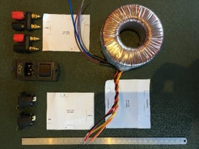
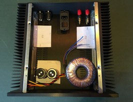
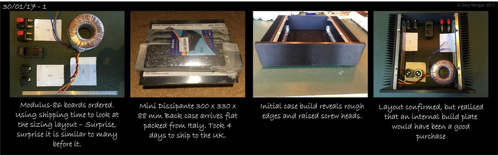
Using the PCB dimensions, I cut-out some paper templates to help size the case. I already had the toroid transformer 25Vac @ 225VA. I placed the amps on either side of the case to allow for maximum heat dissipation. I was going to need something with an internal dimension of at least 220W x 250D x 60H mm more if I were to make the build easier and neater.
Needless to say, I ended up with a layout common to many builds
Apart from the DIY option I did not fine too many case options. There was DOUKAUDIO on eBay, some nice cases but the ones available at the time were a little small. Then I came across Takachi (and these) which were really nice but I could not find any resellers that had the size and finish I was after, so I ended up at Modushop by Hi-Fi 2000, after following the links in diyAudio and purchased a Mini Dissipante 2U 300mm.
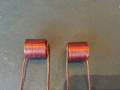
So now I was waiting for parts to arrive so I thought I’d have a go at winding the inductor for the Thiele network. I ordered a small length of 1mm2 enamelled wire from eBay.
 25/01/17:
The wire duly turned up. The suggestion was to wire around a AA battery but I found it a little short to handle with my flippers. So, looking for another 14mm dia. former a found that my small solder sucker was perfect.
Winding the coil tightly I held it in place with a run of Superglue on the top and bottom. Once set I took it off the former and shaped the end connections and then dipped in varnish just to keep the windings neat and in place. Just need to wait for the Mouser order for the resistors.
26/01/16: Mouser order turns up after 4 days from ordering. Check through the packing list and everything is there except for 3 line items (capacitors) that are on back order.
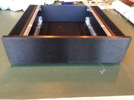
 The HiFi2000 case turns up flat packed from Italy (4 days). I must say I’m a little disappointed in the quality!
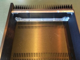
While not exactly sharp there are rough edges on the heatsink fins and galvanised support bars.
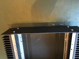
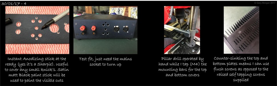
An odd selection of screws is provided. When I say odd, some are too long for the application and need washers (not supplied) to pack them out. Others are spare and must be for other kits. It’s up to you to work out whats what. Raised self-tappers are used to hold the top, bottom plates on. The rear uses a screw and nut arrangement. These would all have been nicer as black threaded counter sinks. So these will probably get swapped out.
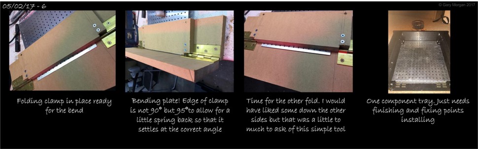
There was the option to purchase an internal build plate but I did not buy it. In hindsight, I’m thinking it might have been a wise move. So, I’m probably going to make one.
With the resistors arriving from Mouser I can complete the Thiele networks. But I’m beginning to regret the additional varnish as it is hard to get good a solder contact. So out came the Dremel to clean up the surface.